Vane Pyrotechnic Valve Actuator
To launch a liquid propellant rocket, valves must open to allow the flow of the fuel and oxidizer into the engine. To help with the development of ‘Purdue Space Program - Liquids’ newest rocket, I was tasked with finding a way to remotely operate our main propellant valves.
Designing
In the past, we have used pyrotechnic valve actuators, which turned the valve stem with pressure generated from a black powder charge. I decided to build on that concept since it was extremely compact for the force it was able to produce.
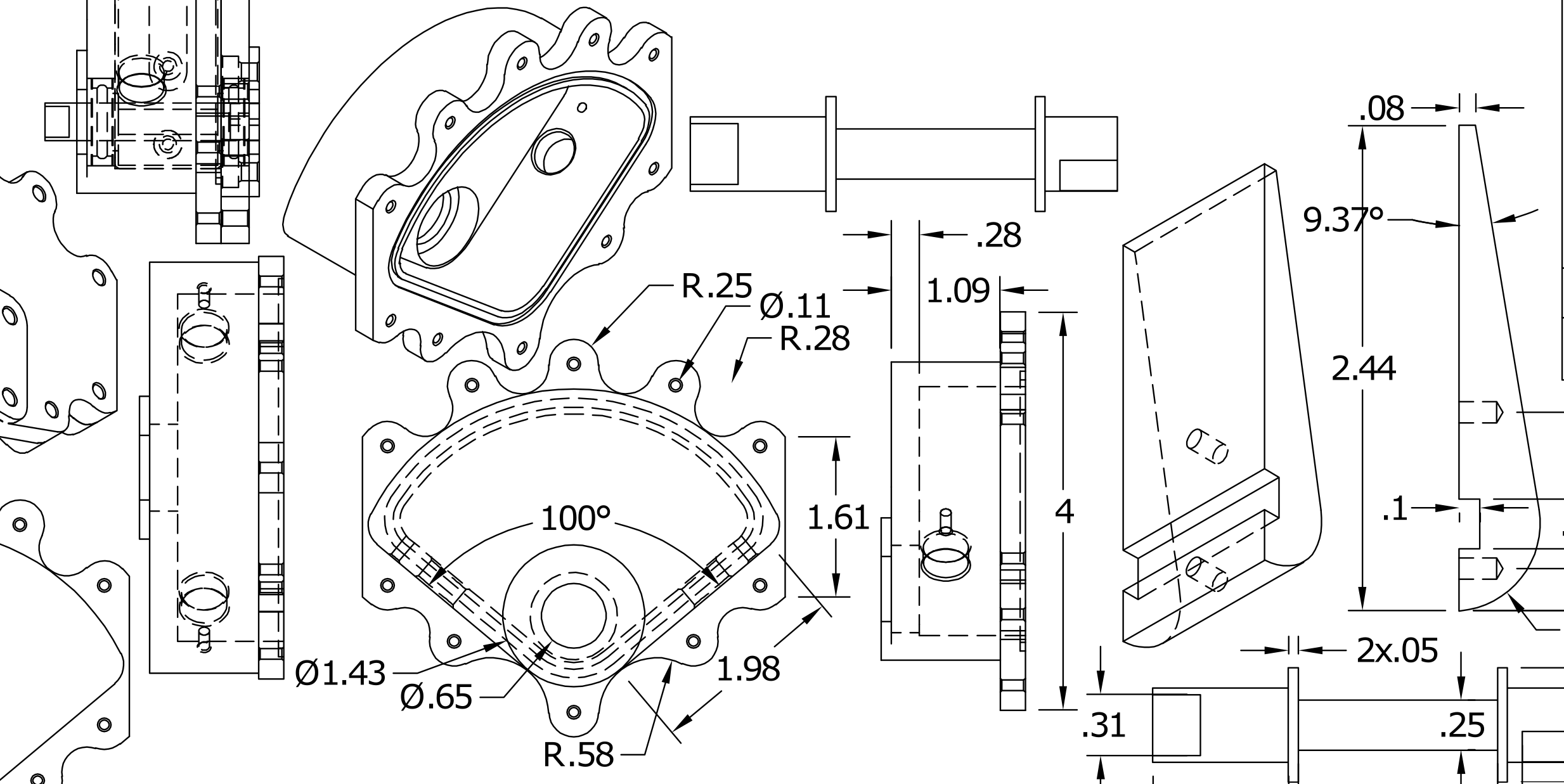
I focused on creating a simple and reliable design, with extra attention on minimizing volume and mass. After countless sketches, I ultimately came up with a design similar to vane actuators. It relied on a paddle connected to the valve’s stem and surrounded by a housing bolted directly to the valve. When a black powder charge is set off, the pressure from the explosion pushes against the paddle and rotates it the required 90 degrees to open the ball valve.
Simulating
When I understood the general design the actuator would have, I started on a simulation script to generate dimensions for the various parts.
Using Python, I wrote a program that modeled the pressure generation from an amount of black powder and used a time-step method to simulate the torque applied to the valve throughout the rotation of the paddle. If the amount of black powder was insufficient to overcome the breaking torque of the valve with an added safety margin, it would fail. Then, it iterated over given ranges of dimensions for different components of the actuator, including paddle width and length, axle diameter and black powder mass. All of the dimension groups that led to successful simulations would be added to a file with priority given to the smallest sized actuator, as that would be ideal for the application.
Once the final dimensions were chosen, I edited the parameters of the actuator CAD model to finish the design.
Manufacturing
This project was the first time I ever worked with a CNC, and it was quite the challenge! I used Fusion360’s CAM software to program the machine paths for all of the 5 parts and a Haas VF4 and UMC-500SS. Luckily, a few of my friends were able to help me through the process.
The housing assembly and both halves of the paddle were machined from 6061 aluminum, and the axle was made of steel since I was concerned aluminum wouldn’t be able to handle the torque transferred from the paddle to the valve stem.
We were able to machine all of the parts on the first go and besides a broken tap, there weren’t any issues with final assembly. Everything turned out great and I was ready to finally put the actuator to the test.
Machining of the axle on UMC-500SS, shown in 200% speed
Testing
To test the actuator, I mated it to a Habonim C47 ball valve, which is what we are using for our LOx line. Two lengths of tube were connected to either side of the valve and secured in place.
Several different sized black powder charges were prepared and we ignited them in the actuator in increasing mass. We were able to get full actuation consistently with 2 grams of black powder.
The video below is of a successful test, and is slowed down to 2% speed and 0.5% speed respectively. The total actuation time was estimated to be under 10 milliseconds. Movement of the axle sticking out of the top of the actuator shows the movement of the paddle within.
Assembled actuator with front panel removed
New actuator with front panel removed
New actuator with front panel
The new actuator will eliminate gaps in any sealing surface to minimize escaping gas. The countersink for the bolt heads now have a seal routed around them and a gap on version-1 was remedied by overlapping the sealing material.
Testing:
The next test will have the valve under normal operating conditions for launch: exposure to flight pressures and cryogenic liquid. This will better test the capabilities of the vane actuator and verify it for flight. In preparation for the testing, a fluids panel and plumbing test system will need to be assembled.
Improvements
Design:
Much was learned from the first iteration vane actuator, and a second version is already designed and set for manufacturing.
Major improvements include…
Better handling of exhaust gases
Better sealing features to mitigate pressure lose
Inclusion of thrust bearings to decrease friction
Smaller volume and lower mass
Easier to manufacture and prepare
Actuator attached to ball valve
Actuator with housing removed, exposing paddle assembly
The five components for the actuator.
Top row, right to left: Housing, Front Plate
Second row: Axle, Paddle Half #1, Paddle Half #2
Testing of version-1 showed areas the high pressure gas leaked from the combustion area, which left soot marks. Examples can be seen near the bolt heads and on the edge of the actuator by the bottom of the image.
Successful actuator testing shown in 2% speed and 0.5% speed


